
Interface definition
Roof penetrations refer to any openings or passages created through roofs in a building to allow for the installation and routing of various utilities and services. These penetrations are essential for the functional and operational aspects of a building, ensuring that necessary systems such as electrical wiring, plumbing, HVAC (heating, ventilation, and air conditioning), and communication cables can be properly installed and maintained.
Examples of building penetrations include:
- Electrical penetrations: Conduits and cables for power distribution and lighting, Data and coms cables.
- Plumbing penetrations: Water supply, drainage and waste management, gas lines for heating.
- HVAC: Ductwork for heating, ventilation and air conditioning systems, vents and flues for exhaust and fresh air intake.
- Fire protection penetrations: Sprinkler systems, fire alarms and detection systems.
Interface requirements
Critical requirements for a roof penetration interface were summarised as follows:
- Low-cost, widely accessible details for Transform-ER.
- Must act as a connection detail between EWI and the existing property.
- Must keep in line with fire regulations and UK building regulations.
- Prevent damp/moisture ingress into the property.
- Provide adequate heat resistance to deal with hot flues.
Interface categorisation
- Insulation risk
- Condensation risk
Interface rules
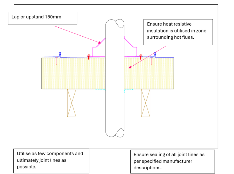
The following are critical high-level rules for a Roof penetration detail that should be complied with as part of a Transform-ER retrofit programme:
- Lap or upstand 150mm
- Ensure heat resistive insulation is used in zone surrounding hot flues
- Use as few components and ultimately joint lines as possible
- Ensure sealing of all joint lines as per specified manufacturer descriptions.
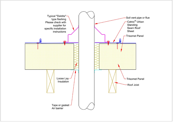
Exemplar detail
Below is an example of how TATA STEEL’s system tackles a roof penetration interface and the steps/procedure put in place to ensure weather tightness, insulative properties and fire resistance are maintained:
Testing and validation
It is important that the system provider considers how any roof upgrade system will accommodate any services penetrations to ensure the claimed roof system performances are not adversely impacted due to this interface. It is also important to ensure no unintended consequences are created.
Roof penetrations are unavoidable in both cold and warm roof constructions. In retrofit scenarios, they pose risks to airtightness, moisture control, fire resistance, and thermal continuity, especially when upgrading with insulation above, below, or between the rafters.
Poor detailing around roof penetrations – such as soil vent pipes, boiler flues, extract ducts, and rooflights – is a common source of condensation, heat loss, and rain ingress. This guide supports manufacturers and designers in detailing robust, compliant, and durable roof penetration interfaces for domestic roof upgrades.
Develop standardised detailing packages
Manufacturers should consider developing detailing guidance for the following roof penetration scenarios:
- Boiler flues and chimney flues – Must maintain safe separation from combustibles and be weatherproofed and fire-stopped.
- Soil vent pipes (SVPs) – Require sealed flashing to prevent water ingress and must maintain thermal and airtight layers.
- Mechanical extract vents /MVHR Ducts – Should pass through roof using insulated ducts with airtight collars and condensation-resistant detailing.
- Roof lights/sun tunnels – Must be sealed and insulated at reveals and upstands, particularly in warm roof systems.
- Aerials and fixing brackets – Require robust sealing around fixings and penetrations without compressing or degrading insulation.
Key design variables include:
- Type of insulation used (between/below rafters or overdeck).
- Vapour control layer position.
- Roof pitch and covering type.
- Ventilation strategy (e.g. vented cold loft or unvented warm roof).
Design detail validation
Roof penetrations are essential but high-risk junctions in upgraded roof systems. Whether passing flues, extract ducts, or rooflights, detailing must ensure that all performance layers – insulation, airtightness, moisture protection, and structural support – are maintained and validated.
Manufacturers should provide tested and repeatable solutions for all common penetration types and align their designs with building regulations and system warranties.
Thermal performance
- Maintain insulation continuity and prevent localised cold spots or condensation around roof penetrations. Use insulated duct sleeves and insulated rooflight reveals.
- 2D or 3D thermal modelling of upstands, flue collars, and vent ducts.
- Psi-value modelling on defined details as per BS EN ISO 10211, BR 497 and BRE IP 1/06.
Airtightness
- Prevent uncontrolled air leakage at pipe, duct, and rooflight penetrations. Seal penetrations at the air barrier (VCL or airtightness membrane) using: Preformed airtight collars, Butyl or EPDM gaskets, Airtight tapes and compatible sealants. Confirm via whole-roof blower door testing.
- BS EN 12114 – Air permeability testing.
Moisture and vapour management
- Prevent condensation and moisture accumulation in or around penetrations. Ensure airtight sealing of internal warm-side penetrations (VCL layer). Provide insulated ducting or sleeves through cold roof spaces. Use hygrothermal analysis for high-risk details (e.g. MVHR vents in warm roofs).
- Modelling – BS 5250:2021 provides guidance on moisture management and assessment approaches e.g. hygrothermal modelling to BS EN 15026 and condensation risk analysis to BS EN ISO 13788.
Weatherproofing & rain resistance
- Prevent water ingress around roof penetrations. Use proprietary flashing kits or weather collars suitable for tile type and pitch. Ensure adequate overlap with underlay and roof covering (e.g. tile battens). Seal penetrations through flat roofs with upstands and weathered flanges.
- BS 5534 – Tiling and slating requirements.
- BS EN 14963 – Flashing kits for rooflights and penetrations.
- BS 8215 guidance for flashings and leadwork detailing.
Fire safety (Flues and heat-producing appliances)
- Prevent fire spread and protect insulation from heat damage. Provide fire-stopping where flues penetrate fire-separating elements. Ensure correct clearances to combustibles around flues and chimneys. Use intumescent collars or wraps for pipe/fire barrier penetrations.
- Approved Document J – Requirements for flues and heat-producing appliances.
- BS EN 13501-1 – Reaction to fire classification.
- BS EN 1366-3 – Fire resistance of service penetrations.
Relevance
- Condensation risk increases where warm air meets cold surfaces, particularly at flue collars and uninsulated ducts.
- Water ingress at poorly sealed flashings or pipe collars can lead to roof deck rot or insulation saturation.
- Cold bridging occurs if insulation is interrupted without compensatory detailing.
- Air leakage around pipes and ducts reduces whole-envelope performance.
- Fire risk arises where flues or chimneys are not separated from combustible insulation layers also need special care if penetrating a fire resisting element.
Site validation
Detailing should be checked after the system is installed to confirm the validity of the proposed designs. Below are post installation checks that may be appropriate.
- Visual confirmation – Check fall direction and water-shedding effectiveness at junction.
- Conduct blower door test (BS EN 12114) to identify leakage points at penetrations
- Use infrared thermography (BS EN 13187) to detect thermal bridging at penetrations.
- Use moisture meters or sensors in warm roof constructions with known risk.