
Interface definition
Penetrations
Penetrations refer to any openings or passages created through walls in a building to allow for the installation and routing of various utilities and services.
These penetrations are essential for the functional and operational aspects of a building, ensuring that necessary systems such as electrical wiring, plumbing, HVAC (heating, ventilation, and air conditioning), and communication cables can be properly installed and maintained.
Examples of building penetrations include:
- Electrical penetrations: Conduits and cables for power distribution and lighting, Data and comms cables.
- Plumbing penetrations: Water supply, drainage and waste management, gas lines for heating.
- HVAC: Ductwork for heating, ventilation and air conditioning systems, vents and flues for exhaust and fresh air intake.
- Fire protection penetrations: Sprinkler systems, fire alarms and detection systems.
Mountings
Building external wall mountings refer to the methods, materials, and techniques used to securely attach various elements to the exterior walls of a building.
These mountings must be designed to withstand environmental factors like wind, rain, temperature fluctuations, and physical stress while also ensuring aesthetic coherence and functional reliability. Common applications include signage, lighting, HVAC units, decorative elements, and security equipment.
Examples of wall mountings include:
- Signage: Signs mounted on brick walls using expansion bolts and sealed with silicone to prevent water entry.
- Lighting: Wall-mounted lights with metal brackets, installed using masonry anchors, and sealed with weatherproof gaskets.
- HVAC Units: Mounted on exterior walls using heavy-duty metal brackets anchored into concrete or masonry with expansion bolts, and with drainage lines properly sealed.
- Awnings: Fabric or metal awnings attached using support arms bolted into brick or concrete, with all joints sealed to prevent water ingress.
- Security Cameras: Cameras housed in weatherproof enclosures mounted on adjustable brackets, secured with stainless steel screws and sealed to protect wiring connections.
Interface requirements
Critical requirements for the party wall interface were summarised as follows:
- Low-cost, widely accessible details for Transform-ER.
- Must act as a connection detail through EWI to the existing property.
- Must retain insulative properties as similar to EWI performance as possible.
- Prevent damp/moisture ingress into the property.
- Should be standardised where possible.
- Should support loading conditions required by ancillary equipment.
Interface categorisation
- Insulation risk
- Structural risk
Interface rules
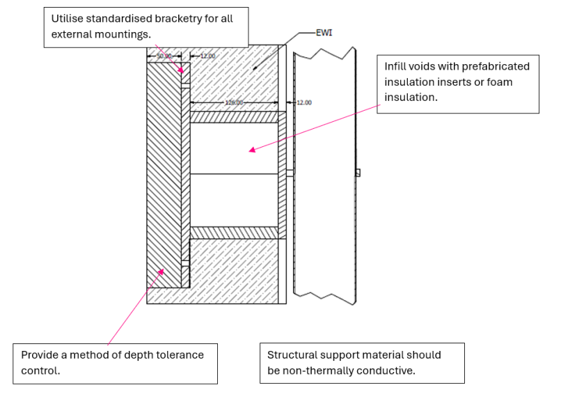
The following are critical high-level rules for wall penetration or mounting details that should be complied with as part of a Transform-ER retrofit programme:
- Use standardised bracketry for all external mountings
- Infill voids with prefabricated insulation inserts or foam insulation
- Provide a method of depth tolerance control
- Structural support material should be non-thermally conductive.
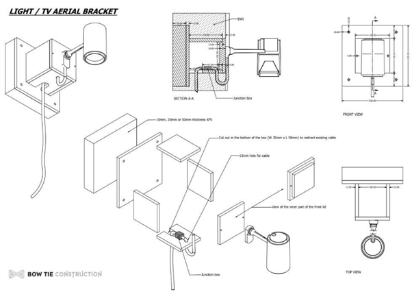
Exemplar detail
The below details demonstrate how Bow Tie Construction have designed a universal bracket than can be cross applicable to multiple wall penetration/mounting applications including water taps, light fixtures and guttering downpipe mountings:
Testing and validation
It is important that the system provider considers how the external wall system will accommodate service penetrations and fixtures which are fixed through or attached to the external wall system, to ensure the claimed system performances are not adversely impacted due to this interface. It is also important to ensure no unintended consequences are created.
Service penetrations – such as vents, ducts, pipes, cables, and flues – are unavoidable in domestic retrofit projects, yet they often become weak points in external wall insulation (EWI) systems. Poorly detailed penetrations can introduce thermal bridges, moisture ingress, air leakage, and fire safety risks.
In retrofit external wall insulation (EWI) systems, fixing items to or through the insulated façade can compromise the thermal envelope, introduce air or water leakage, or create structural risks. From clothes lines, satellite dishes and external lights to service boxes, signage or rainwater goods, all mounts must be designed and installed to maintain the system’s integrity, durability, fire safety, and regulatory compliance.
This guide outlines how manufacturers should develop, validate, and support robust solutions for common service penetrations and wall fixing methods through retrofit external wall upgrades.
Develop standardised detailing packages
Service penetrations are often overlooked but critical parts of retrofit detailing. Each type — from simple cable runs to gas risers and boiler flues — requires bespoke, validated detailing that preserves insulation continuity, moisture protection, and fire safety. Manufacturers must supply standardised details and ensure clear installation guidance is provided to site teams.
Robust penetration detailing not only protects system performance and safety but also underpins compliance with Building Regulations and certification schemes such as BBA, SWIGA, and PAS 2035.
Manufacturers should consider developing a range of system-compatible detail options for the following service types:
- Background air vents – Passive vents that pass through the wall to ventilate habitable spaces. Should include a weatherproof sleeve that maintains airflow while preventing bridging and water ingress.
- Cold extract vents – Typically from MEV/MVHR systems or kitchen fans with cool discharge air. Require vapour-tight ducting and thermal collars if penetrating through thick insulation layers.
- Hot extract vents – Discharge humid air from bathrooms, dryers, or cookers. Must be sealed with high-temperature-compatible ducting and fitted with insulated collars or sleeves to prevent condensation and thermal bridging.
- Gas pipe risers – Often external; must not be buried within insulation. Require stand-off brackets, visible routing, and fire-resistant collars at penetration points.
- Electrical cables – Telecoms, satellite, or mains wiring must be routed through flexible sleeves or grommets. Airtight seals required with weather-grade mastics; fire collars used if passing into protected zones.
- Flues – Serve gas boilers, stoves, or biomass appliances. Require compliant separation from combustibles, fire-stopping, and visible access. Should use stand-off brackets, intumescent collars, and weatherproof sealing compatible with external finish e.g. render.
For fixtures, a range of system-compatible detail options should be considered:
- Lightweight fixtures (typically <5 kg) – Examples: External lights, cameras, alarm boxes, small signage. Typically require surface-mounted fixing into the outer render layer or insulation, with appropriate dowels or plugs.
- Medium to heavyweight fixtures (5–25 kg) – Examples: Hanging baskets, downpipes, wall-mounted garden equipment. Must be mechanically anchored back to the structural wall, bypassing insulation to avoid load on render or insulation alone.
- Large or structural items (>25 kg or large area contact) – Examples: Service meter boxes, gas/electric cupboards, air source heat pump brackets. Require dedicated fixing back to structural substrate with compression sleeves or thermal break mounting kits.
Common fixture types to consider:
- Satellite dishes and aerial brackets.
- Meter boxes (gas/electric).
- Rainwater downpipes and brackets.
- Cable trays or electrical conduits.
- Signage or nameplates.
Generic details and guidance are available in INCA Technical Guidance Document 06.
Design detail validation
Service penetrations must be validated for their impact on thermal continuity, moisture resistance, airtightness, and fire performance.
Wall-mounted fixtures are often retrofitted after insulation is applied, and without proper detailing, they can undermine the entire system’s performance. Manufacturers must provide clear, standardised mounting strategies that maintain the wall system’s thermal continuity, airtightness, water resistance, and structural reliability.
All fixings should be compatible with the render system and installed using tested and approved methods. Fixing components to or through external wall upgrade systems introduces risks to structural performance, thermal continuity, weather resistance, and fire safety.
The following breakdown outlines how each aspect should be addressed through recognised modelling, testing, or guidance:
Structural load resistance
- Ensure fixtures are mechanically supported without damaging the insulation or render. Select fixings rated for substrate type (e.g., brick, block). Perform pull-out resistance testing where needed, especially for large or dynamic loads (e.g. satellite dishes). Use compression sleeves or stand-off systems to bypass insulation for heavy fixtures.
- BS EN 1991-1-4 – Wind loading and structural actions.
- BS EN 13494 – Pull-out resistance of EWI anchors.
- BRE Digest 365 – Fixing into masonry and substrate conditions.
Thermal performance
- Ensure insulation continuity and reduce cold bridging at penetrations (e.g. flues, large ducts) and through high-conductivity fixings or mounting plates. Local insulation collars or flexible fill materials to maintain insulation continuity. For fixing, use thermal isolators (e.g., plastic sleeves, washers, thermal breaks).
- Psi-value modelling on defined details as per BS EN ISO 10211, BR 497 and BRE IP 1/06.
Airtightness
- Prevent uncontrolled air leakage around ducts, cables, and pipes. Specify flexible grommets, airtight sleeves, and sealants tested for movement and ageing. Whole-dwelling air leakage testing to confirm system performance.
- For fixings, maintain the air control layer and prevent leaks at fixing penetrations. Use of airtight sleeves, tapes, or compressive seals. Include sealing of cable/pipe fixings during or immediately after installation. Confirm through post-installation air tightness test.
- BS EN 12114 – Air permeability testing method.
Moisture and vapour management
- Prevent interstitial condensation and moisture ingress through or around penetrations. Use of weather-sealed collars or flashings at all external terminations. Vapour-tight ductwork to prevent condensation within insulation layers. Hygrothermal simulation in complex cases. For fixings, test for freeze-thaw durability and render compatibility.
- Modelling – BS 5250:2021 provides guidance on moisture management and assessment approaches e.g. hygrothermal modelling to BS EN 15026 and condensation risk analysis to BS EN ISO 13788.
- EAD 040083-00-0404 – Freeze-thaw and durability for EWI components.
- BS EN ISO 15148 – Water absorption by capillarity.
Water ingress resistance
- Ensure driving rain, splashback, or standing water does not track behind system via penetrations.
- Use of proprietary external collars, over-sleeves, or mastic sealing. Render-compatible kits with proven weather resistance.
- Prevent water ingress into or behind the EWI system at fixing points.
- Ensure use of EPDM grommets, compression collars, or external-grade sealants at all penetrations.
- BS 8104 – Assessing wind-driven rain exposure (design tool).
- Water ingress test data where available.
Fire performance
- Prevent flame spread or compromise to fire compartments via penetrations (especially flues and gas pipes). Use of fire collars, intumescent wraps, and non-combustible sleeves. Check compatibility with insulation reaction to fire classification.
- BS EN 13501-1 – Reaction to fire classification.
- Approved Document J – Clearances and flue performance
All service penetrations should preserve the integrity of the insulation, air barrier, and weatherproofing layers. Fire resistance requirements must be met if the penetration is through an external wall performing a fire resistance function e.g. due to proximity to adjacent buildings.
Durability & system compatibility
- Ensure fixings perform for the life of the system without causing cracking, detachment, or corrosion. Use of system-approved fixings tested for compatibility with the insulation and render. Validation through accelerated ageing tests where applicable.
- EAD 040083-00-0404 – Impact resistance, durability, and ageing for EWI.
Relevance
- Air leakage at cable and pipe entries undermines the building’s airtightness strategy.
- Cold bridging around plastic ducts or metal flues can cause condensation and mould.
- Water ingress at unsealed vents or risers can lead to render failure and insulation saturation.
- Fire spread can occur if combustible services penetrate EWI without proper collars.
For fixings:
- Moisture ingress behind insulation from unsealed fixings.
- Render cracking or detachment due to excessive localised load.
- Cold bridging, especially with steel brackets or fixings without isolation.
- Fixture detachment in high winds, posing safety risks to people or property.
Site validation
Detailing should be checked after the system is installed to confirm the validity of the proposed designs. Below are post installation checks that may be appropriate.
- Visual confirmation – Check fall direction and water-shedding effectiveness at junction.
- Conduct blower door test (BS EN 12114) to confirm air leakage control.
- Use infrared thermography (BS EN 13187) to detect cold bridging at major penetrations.
Fixings:
- Structural testing – On-site pull-out testing for unusual or heavy fixings (e.g., ASHP brackets or large boxes).
- Thermal imaging (BS EN 13187) – Detect bridging around multiple fixings or metal contact points.