
Interface definition
A party wall is a wall that stands on the boundary line between two adjoining properties, providing shared structural support. These walls are commonly found in terraced houses, semi-detached houses, and some commercial buildings.
Key components of party walls are:
- Foundation: The party wall starts with a shared foundation that extends across the boundary line. The foundation needs to be designed to support the loads from both properties.
- Wall structure: Masonry in traditional builds, either brick or breeze blocks. Sometimes a double layer stud wall in modern builds.
- Fire resistance materials and construction: Wall must be continuous from foundation to roofline including attics using specific brick, blockwork and drywall types.
- Insulative material: Airgaps and insulative material utilised to provide sound insulation.
- Wall ties, connectors, plastering and finishing.
Within the interface grouping party wall interaction with the roof, walls, floor and chimneys will be covered.
Interface requirements
Critical requirements for the party wall interface were summarised as follows:
- Low cost widely accessible details for Transform-ER.
- Must act as a connection detail between EWI and the existing property.
- Must keep minimum opening sizes in line with fire regulations and UK building regulations.
- Prevent damp/moisture ingress into the property.
- Ensure insulation and thermal properties are continuous across the interface.
Interface categorisation
- Fire risk
- Condensation risk
Interface rules
The following are critical high-level rules for a party wall detail that should be complied with as part of a Transform-ER retrofit programme:
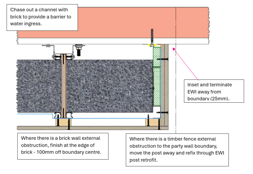
- Chase out a channel with brick to provide a barrier to water ingress.
- Inset and terminate EWI away from boundary (25mm).
- Where there is a brick wall external obstruction, finish at the edge of brick – 100mm off boundary centre.
- Where there is a timber fence external obstruction to the party wall boundary, move the post away and refix through EWI.
Interoperability rules
- If fitting a new system to a property with existing EWI, remove adjoining finishes back to cement board layer.
- Remove first 20mm of existing front facing façade and refinish with blended joint post retrofit.
- Never create a cavity between existing EWI system and New system.
- Ensure a firebreak is created between systems, this could be the render reveal.
Extensions rules
- Any gap between extensions less than 200mm should be completely filled with rockwool or have an air pocket created by encapsulating perimeter 200mm.
- Flashing on top of extension joint is essential.
- Finish EWI around extension if the extension is a bathroom or non-living space.
- If the extension is a 70’s style extension complete improvement works (mould prevention paint, extract fan upgrades, gap filling) instead of EWI.
Loft party wall rules
- Fill chimney stacks with rockwool and foam insulation, slate over the top.
- Ensure air bricks are left in chimney zone to allow for loft ventilation and enable chimney to breathe.
- Loft insulation should not be installed up to eaves.
Exemplar detail
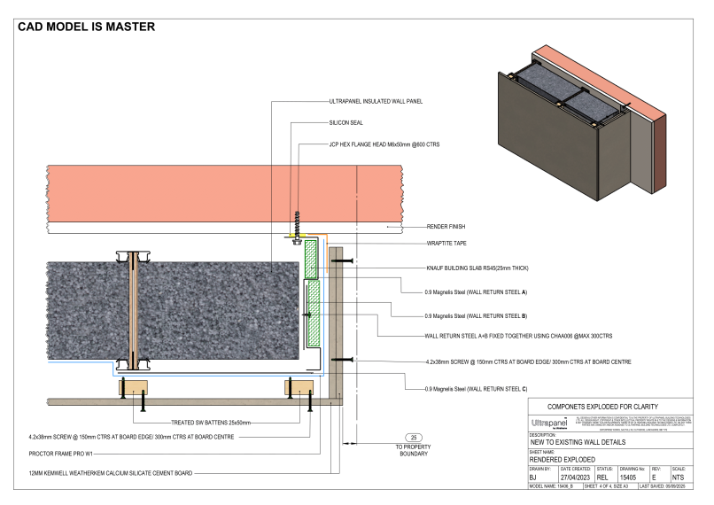
Below is an example of how Ultraframe’s system tackles a Party Wall interface and the steps/procedure put in place to ensure weather tightness, insulative properties and fire resistance are maintained:
Testing and validation
It is important that the system provider considers how the party wall interfaces with external wall system to ensure that the claimed system performances are not adversely impacted due to this interface. It is also important to ensure no unintended consequences are created.
Party wall junctions present unique challenges in retrofit projects, especially when only one side of a semi-detached or terraced dwelling is being upgraded. These junctions are often sources of thermal bridging, air leakage, and moisture accumulation if not properly detailed.
This guide outlines how to develop and validate robust junction solutions for connections between the external wall insulation (EWI) system and party walls, roofs, and chimneys, with a particular focus on scenarios where only one side of a shared structure is treated.
Develop standardised detailing packages
Party wall junctions require specific detailing to manage thermal and moisture risks, especially in semi-detached or terraced dwellings where only one side is upgraded. By wrapping insulation partially around party walls, maintaining air control layers, and avoiding moisture traps in cavities, manufacturers can deliver more resilient, efficient systems.
Designs must reflect the complexity of shared structures and incorporate both physical protections (e.g. cavity closers) and simulation evidence (e.g. thermal modelling) to support certification and compliance.
Manufacturers should consider developing a range of standard detail options for the following common junctions:
- External wall to party wall: where EWI stops at or wraps onto a party wall return.
- Party wall to pitched roof or loft void: at the top of gables or shared lofts.
- Chimney party walls: where shared chimneys are set within or project from party walls.
- Internal floor-to-party wall junction: where EWI may wrap internally at gable ends.
- Half-upgraded homes: semi-detached or terraced properties where EWI is only applied to one unit.
Key variables include:
- Whether party walls project externally (as with stepped gables).
- Wall type (solid vs cavity).
- Party wall thermal continuity — especially above ceiling level.
- Whether the party wall is treated, exposed, or shared.
Generic details and guidance are available in INCA Technical Guidance Document 06.
Design detail validation
Verge junctions in external wall upgrade systems must be assessed to ensure they deliver performance across five key areas: thermal continuity, moisture resilience, airtightness, structural durability, and fire safety. The following table sets out the evaluation approach for each performance category using recognised testing, modelling, or design guidance:
Thermal performance
- Modelling of junctions at gables, chimneys, and party wall returns. Where EWI terminates at a party wall (semi-detached), use thermal break return (e.g., 300–600 mm insulated return onto party wall). Modelling of loft void heat loss via party wall cavities (consider if open to atmosphere).
- Psi-value modelling on defined details as per BS EN ISO 10211, BR 497 and BRE IP 1/06 and SAP Appendix K.
Airtightness and wind penetration
- Detail must ensure air leakage and thermal bypass do not occur at untreated party walls. Use closers, tapes, or returning insulation layers to reduce bypass risk.
- Blower door testing (BS EN 12114) and/or infrared imaging (BS EN 13187) to verify performance.
Moisture management
- Where party wall cavities exist, moisture movement between properties must be considered: Avoid driving moisture behind insulation at exposed cavity stops. Where one side is untreated, stop ends and breathable membranes may be required to maintain ventilation.
- Modelling – BS 5250:2021 provides guidance on moisture management and assessment approaches e.g. hygrothermal modelling to BS EN 15026 and condensation risk analysis to BS EN ISO 13788.
Chimney detailing
- Ensure chimney flanks or stacks integrated into party walls are: Protected against freeze-thaw and not bridged thermally.
Sound insulation
- When upgrading lightweight framed (timer or steel) dwellings care should be taken to ensure a flanking transmission path is not created that bridges the existing designed in continuity breaks.
Relevance
- Cold bridging at the edge of untreated party walls increases risk of mould, especially near ceilings or under eaves.
- Inter-unit air leakage can compromise heating efficiency and cause discomfort in both properties.
- Moisture accumulation in party wall cavities is a known cause of post-retrofit failure, especially where insulation is returned without ventilation or drainage paths.
Site validation
Detailing should be checked after the system is installed to confirm the validity of the proposed designs. Below are post installation checks that may be appropriate.
- Thermal imaging (BS EN 13187) – of internal surfaces to check cold bridge performance (party wall junctions at ceiling and eaves).
- Blower door testing (BS EN 12114) – Verify airtightness performance to check for leakage at returned or bridged junctions.