Interface definition
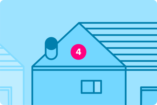
A verge, also known as the gable or eaves overhang, is the edge of a roof that extends over the end wall of a building. The verge is an important architectural detail that serves both functional and aesthetic purposes.
Common components that form part of a verge interface are:
- Gable end: The triangular portion of the end wall that extends from the eaves to the ridge of the roof.
- Rafter ends: The ends of the rafters that project beyond the gable end wall to support the verge.
- Bargeboards: Decorative boards attached to the projecting rafter ends at the gable end. Bargeboards provide protection and add an aesthetic element to the roofline.
- Verge boards: Boards that run along the edge of the roof at the gable end, covering the exposed rafter ends and often providing additional decorative detail.
- Undercloak and overcloak: In traditional roofing, an undercloak is a layer of protective material (e.g., slate or cement) placed under the edge of the roof covering (tiles or slates), and the overcloak is the actual roof covering that extends over the verge.
Interface requirements
Critical requirements for the verge interface were summarised as follows:
- Low cost widely accessible details for Transform-ER.
- Must act as a connection detail between EWI and the existing property.
- Must keep in line with fire regulations and UK building regulations.
- Prevent damp/moisture ingress into the property.
- Ensure insulation and thermal properties are continuous across the interface.
Interface categorisation
- Fire risk
- Structural risk
- Insulation risk
- Condensation risk
Testing and validation
It is important that the system provider considers how the external wall interfaces with verges to ensure that the claimed system performances are not adversely impacted due to this interface.
The verge is the junction where the external wall system meets the sloping edge of a pitched roof, typically at a gable wall. This interface is highly exposed and must manage wind-driven rain, thermal continuity, airtightness, and roof-covering compatibility. It may also intersect with ventilation paths and structural components like rafters or verge overhangs.
Poor detailing can result in water ingress, render failure, thermal bridging, or even structural damage. This guide supports manufacturers in creating robust, validated verge details for use in domestic retrofit applications.
Develop standardised detailing packages
Verge detailing is a crucial part of the external wall upgrade system.
Manufacturers should design junctions that manage weather exposure, thermal continuity, air control, and structural durability, while allowing compatibility with a wide range of existing roof types and conditions. By offering standardised, tested verge solutions — including for both flush and projecting gables — manufacturers help installers reduce risk, maintain performance, and deliver systems that meet regulatory and certification requirements.
Manufacturers should consider developing a range of system-compatible detail options for the following common verge scenarios:
- Flush verges with minimal overhang (typical in terraced properties).
- Projecting verges with rafters or purlins protruding beyond the gable.
- Verges with bargeboards or verge tiles overlapping the wall.
- Exposed gables with verge trims (e.g. concrete tile edge pieces or dry verge systems).
- Verges with room-in-roof conversions, where ceiling or party walls terminate at the gable.
Key considerations include:
- Continuity of insulation to the roof edge.
- Interface between EWI and roof coverings or verge systems.
- Protection of insulation from wind-driven rain and UV.
- Prevention of cold bridging where internal ceiling or loft abuts uninsulated gable areas.
- Airtightness at ceiling level or party wall junctions.
Generic details and guidance are available in INCA Technical Guidance Document 06.
Design detail validation
Verge junctions in external wall upgrade systems must be assessed to ensure they deliver performance across five key areas: thermal continuity, moisture resilience, airtightness, structural durability, and fire safety. The following table sets out the evaluation approach for each performance category using recognised testing, modelling, or design guidance:
Thermal performance
- Prevent heat loss and surface condensation risks at the top of the gable wall and ceiling junction.
- Psi-value modelling on defined details as per BS EN ISO 10211, BR 497 and BRE IP 1/06.
- Confirm insulation continuity between wall and roof, including any required insulation returns or loft overlap
Moisture management and wind-driven rain
- Prevent rainwater ingress at verge edge where render and insulation meet roof elements or tiles. Design verification of overlap and verge flashing or closers. Integration with existing or new verge trims (e.g. dry verge, bargeboards) to shed water.
- Modelling – BS 5250:2021 provides guidance on moisture management and assessment approaches e.g. hygrothermal modelling to BS EN 15026 and condensation risk analysis to BS EN ISO 13788.
- BS 8104 – Wind-driven rain exposure assessment.
- BS 5534 – Slating and tiling for pitched roofs (roof verge compatibility).
Airtightness
- Maintain continuous air control layer at the gable/ceiling junction, particularly in lofted or party wall scenarios. Use of vapour control layers or airtight membranes returned and sealed to the structure. Ensure continuity of membranes where insulation is interrupted. Confirm integrity through blower door testing at dwelling level.
- BS EN 12114 – Air permeability test method.
Structural durability
- Ensure verge trims and render edges withstand wind uplift, freeze-thaw cycles, and UV exposure. Mechanical fixing of verge closers or beads to load-bearing structure. Testing of system edge durability using accelerated ageing protocols.
- EAD 040083-00-0404 – Durability testing of EWI systems.
- BS EN 1991-1-4 – Wind loading for fixings and system components.
Fire resistance (where applicable)
Prevent flame spread where the verge detail crosses or adjoins a boundary or shared roof structure. Assess insulation and verge finish for Euroclass classification. Use non-combustible trims, boards, or closers where required by proximity to boundary.
- Approved Document B – Fire safety in dwellings (boundary conditions).
- BS EN 13501-1 – Reaction to fire classification.
Relevance
- Water ingress is common at verges due to wind-driven rain, particularly with ageing tiles or poor verge trims.
- Cold bridging occurs at gable loft junctions or ceiling line returns if insulation is not continuous.
- Render cracking and detachment may occur if verge fixings are weak or not resistant to roof movement.
- Air leakage and heat loss is common at the party wall/ceiling level where uninsulated junctions exist.
- Fire spread risk can increase where verge abuts or crosses a property boundary (e.g. terrace).
Site validation
Detailing should be checked after the system is installed to confirm the validity of the proposed designs. Below are post installation checks that may be appropriate.
- Visual confirmation – Check fall direction and water-shedding effectiveness at junction.
- Thermal imaging (BS EN 13187) Infrared thermography – Assess for cold bridging at ceiling line or under roof verge.
- Blower door testing (BS EN 12114) Airtightness testing – Whole-building test can identify leakage at the top of gable wall or ceiling junction.