
Interface definition
The base-to-ground interface of a building, also known as the foundation or the footing interface, is a critical area that ensures the structural stability and longevity of the building. This interface includes several components and considerations that work together to distribute loads, manage moisture, and provide insulation.
Common components that form part of a base to ground interface are:
- Foundation: The primary support structure that transfers the load of the building to the ground.
- Footings: Concrete structures that spread the load from the foundation walls to the soil.
- Drainage system: Installed to manage water around the foundation, preventing water accumulation that can cause damage.
- Vapour barrier: A layer of material, such as plastic sheeting, placed under the foundation slab to prevent moisture from rising into the building.
- Insulation: Used to reduce heat transfer between the ground and the building interior.
- Foundation wall: The vertical element of the foundation that supports the above-ground structure.
Interface requirements
Critical requirements for the base-to-ground interface were summarised as follows:
- Low cost widely accessible details for Transform-ER.
- Must act as a connection detail between EWI and the existing property.
- Prevent damp/moisture ingress into the property.
- Ensure insulation and thermal properties are continuous across the interface.
Interface categorisation
- Insulation risk
- Condensation risk
Interface rules
The following are critical high-level rules for base-to-ground detail that should be complied with as part of a Transform-ER retrofit programme:
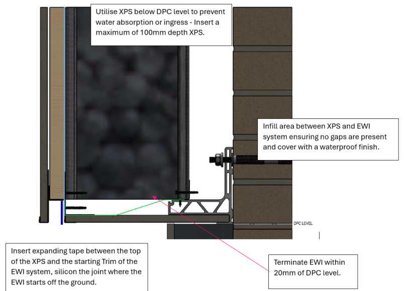
- Use XPS below DPC level to prevent water absorption or ingress – insert a maximum of 100mm depth XPS
- Infill area between XPS and EWI system ensuring no gaps are present and cover with a waterproof finish
- Insert expanding tape between the top of the XPS and the starting trim of the EWI system, silicon the joint where the EWI starts off the ground
- Terminate the EWI within 20mm of DPC level
- Verify DPC level prior to work commencement, DPC level often isn’t ground level.
Exemplar detail
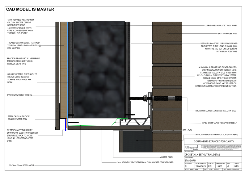
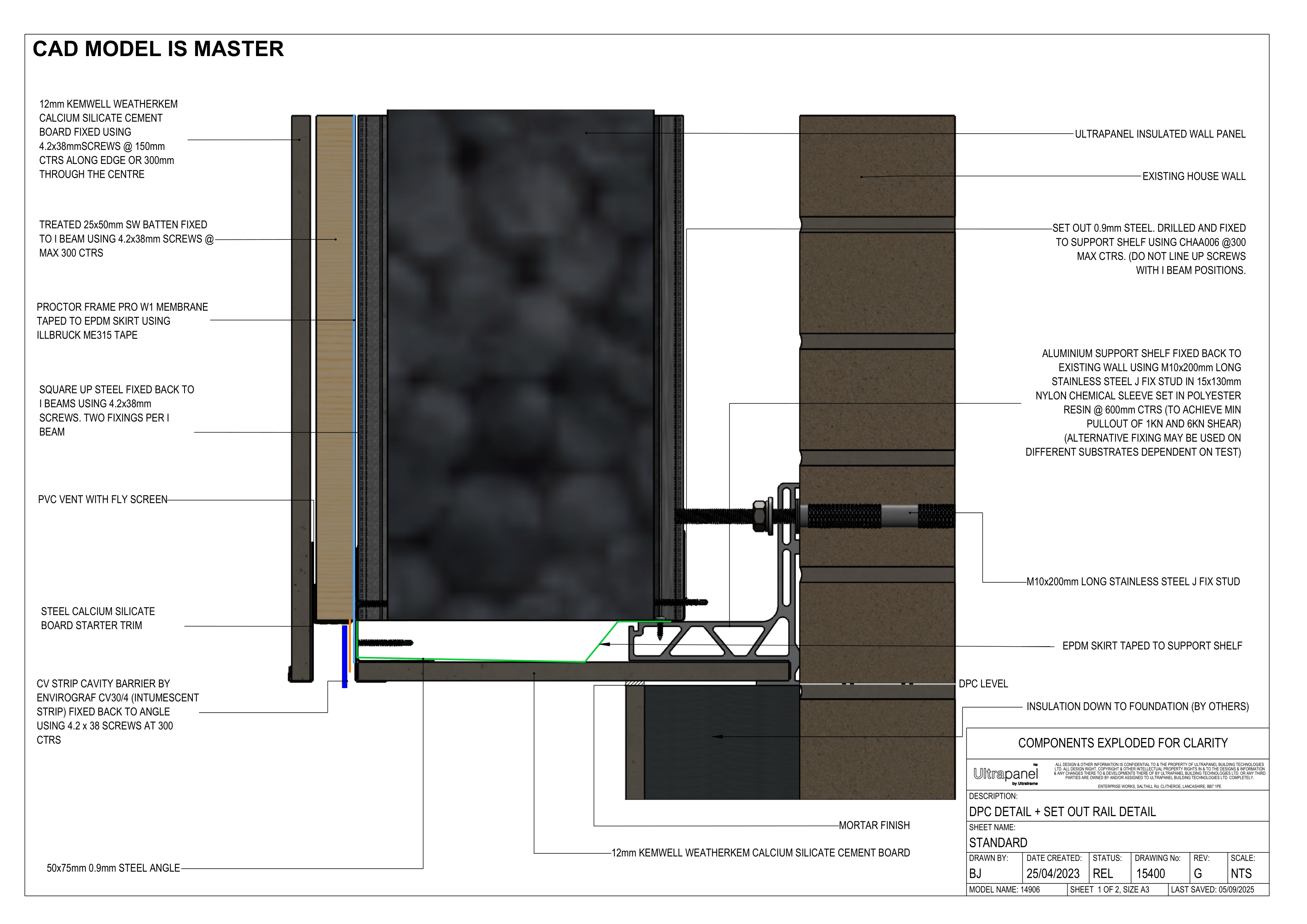
Below is an example of how Ultraframe’s system tackles a base-to-ground interface and the steps/procedure put in place to ensure weather tightness, insulative properties and fire resistance are maintained:
Testing and validation
It is important that the system provider considers how the external wall interfaces with the ground to ensure that the claimed system performances are not adversely impacted due to this interface.
The external wall-to-ground interface is a critical point of continuity in any external wall upgrade system, whether applied internally or externally. It can present risks of heat loss, moisture ingress, material degradation, and compromised air tightness if not carefully designed and validated.
This guide supports manufacturers in developing robust, repeatable system solutions for this junction in domestic properties, helping demonstrate fitness for purpose in typical retrofit applications.
Develop standardised detailing packages
Manufacturers should consider developing a range of system-compatible detail options that accommodate common wall-to-ground interface scenarios laid out below.
Ground levels and DPC height – Variability in the external ground level compared to the internal floor and DPC, Condition and location of the existing DPC (where present).
Decision to insulate below DPC or terminate above – Where insulation is carried below the DPC, risk of moisture ingress and capillary action must be controlled. Where insulation is terminated above, cold bridging must be minimised through offsetting and edge detailing.
These should be designed for a range of common exterior wall types and door/window configurations. Generic details and guidance are available in INCA Technical Guidance Document 06.
Design detail validation
Thermal performance
- Prevent heat loss at ground-to-wall junction and reduce cold bridging.
- Psi-value modelling on defined details as per BS EN ISO 10211, BR 497. and BRE IP 1/06.
Moisture performance
- Modelling – BS 5250:2021 provides guidance on moisture management and assessment approaches e.g. hygrothermal modelling to BS EN 15026 and condensation risk analysis to BS EN ISO 13788.
- Drainage and splashback – Detailing should shed water away from the wall, using render stops, drips, and breathable finishes. Drained cavity systems should provide clear egress at the base.
Structural performance
When evaluating the structural integrity of an EWI system manufacturers should consider:
- Fixing and support strategy – Whether the system is adhesive, mechanically fixed, or hybrid, fixings at the base must be appropriately specified for load, moisture exposure, and long-term durability. Fixing Load Tests at base BS EN 1991-1-4.
- Material durability at ground level:
- Lower sections of the system are more vulnerable to mechanical damage, frost, and splashback. Robust base tracks, reinforced mesh, and impact-resistant render finishes are recommended.
Relevance
- Poorly designed wall-to-ground details can lead to significant performance failures, including:
- Thermal bridging at the base junction causing heat loss and cold floors.
- Moisture ingress through bridging of the DPC or inadequate splash protection.
- Condensation and mould growth from interstitial moisture accumulation.
- Material degradation at the base due to freeze-thaw, capillary rise, or biological decay.
- Compromised air tightness, especially where mechanical fixings or detailing are inconsistent.
- System detachment or movement due to poor substrate adhesion or unsupported sections.
- These issues can undermine overall system performance, reduce lifespan, and contribute to occupant discomfort and health risks. Inconsistent or unvalidated designs may also jeopardise certification outcomes or limit marketability of the system
Site validation
Detailing should be checked after the system is installed to confirm the validity of the proposed designs. Below are post installation checks that may be appropriate.
- Visual confirmation – Check fall direction and water-shedding effectiveness at junction.
- Thermal imaging (BS EN 13187) – Check for cold bridges at base of wall.
- Blower door testing (BS EN 12114) – Verify airtightness performance.
- Moisture testing (BS 5250) – Ensure materials remain dry post-installation.