Interface definition
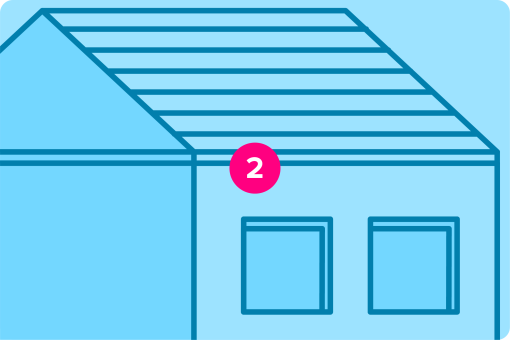
Eaves are an essential component of a building’s roof, extending beyond the walls to provide protection from the elements and contribute to the architectural style.
Typically, eaves consist of the following components:
- Fascia Board: The vertical finishing edge attached to the ends of the rafters or trusses.
- Soffit: The underside of the eaves, which can be enclosed or exposed. The soffit protects the underside of the roof overhang and can be ventilated to allow airflow into the attic space.
- Gutter and downspout: The gutter runs along the edge of the roof, collecting rainwater and directing it to the downspout, which channels the water away from the building’s foundation.
- Drip edge: A metal flashing installed at the roof’s edge, directing water away from the fascia and into the gutter, preventing water infiltration and damage to the roof’s structure.
- Ventilation: Soffits often include vents to allow airflow into the attic, helping to regulate temperature and moisture levels, which can prevent issues like mould growth and ice dams.
There are generally considered to be three types of eave – closed, open and boxed.
Interface requirements
Critical requirements for an eaves interface were summarised as follows:
- Low-cost widely accessible eaves detail for Transform-ER.
- Must act as a connection detail between EWI and the existing property.
- No works to be done on the existing roof.
- Allow through ventilation into the loft space.
- Keep soffit and fascia in line with neighbouring properties.
Additionally, critical challenges were identified when providing an example of a standardised eaves detail:
- Continuity of insulation between roof and wall through the eaves to minimise thermal bridging and thermal bypasses at the junction.
- Continuity of the air barrier, where the air barrier can follow different paths depending on the location of roof and wall insulation.
- Provision of adequate, unhindered ventilation, where the ventilation paths can vary based on the location of roof insulation and the roof geometry; and can be made more challenging when eaves are to be extended.
- Detailing of the VCL, where the VCL in the roof ought to lead into the gutter to allow drainage, but many older roofs do not feature a VCL and the EEM might not normally involve work that would add a VCL (horizontal loose lay loft insulation)
- Thermal bypasses in uninsulated cavity walls with EWI applied (likely an atypical solution), requiring the cavity to be sealed.
- Approaches and details for chimneys which can form large thermal bridges and moisture problems both from the thermal bridging and due to its connectivity with the occupied space.
- Extension of roof line and potential to interfere with window opening below.
Interface categorisation
- Fire risk
- Structural risk
- Insulation risk
- Condensation risk
Interface rules
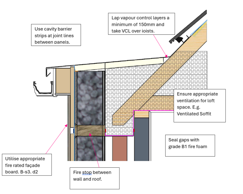
The following are critical high-level rules for an eaves detail that should be complied with as part of a Transform-ER retrofit programme:
- Use cavity barrier strips at joint lines between panels
- Lap vapour control layers a minimum of 150mm and take VCL over joists
- Ensure appropriate ventilation for loft space eg ventilated soffit
- Use appropriate fire rated façade board
- Fire stop between wall and roof
- Seal gaps with grade B1 fire foam.
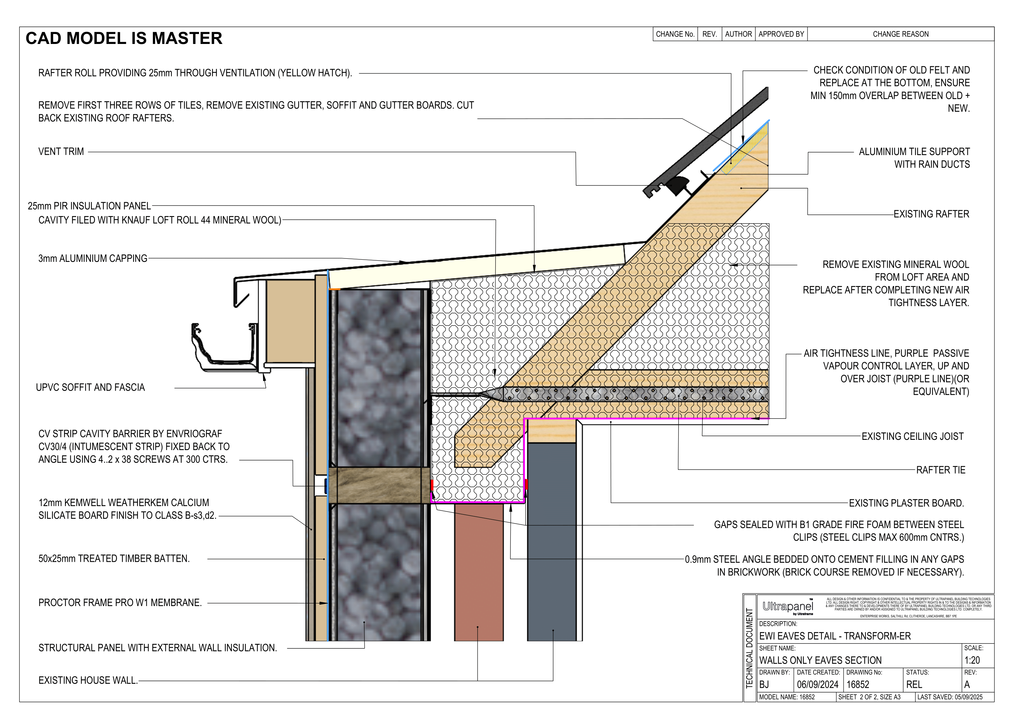
Exemplar detail
Below is an example of how Ultraframe’s system tackles an eaves interface detail, and the steps/procedure put in place to ensure weather tightness, insulative properties and fire resistance are maintained:

Testing and validation
It is important that the system provider considers how the external wall interfaces with the eaves and guttering to ensure that the claimed system performances are not adversely impacted due to this interface.
The external wall-to-roof interface is a critical junction requiring tailored detailing and validation. Using modelling, proven construction details, and robust inspection practices will ensure that systems remain thermally efficient, moisture resilient, and durable over the long term.
Manufacturers should consider providing a range of system-compatible detail options clearly noting any site-specific adaptions required.
Develop standardised detailing packages
When upgrading the external fabric of a domestic property, the junction between the external wall system and the roofline must account for a variety of conditions. Typical situations include:
- Eaves junctions (with pitched roofs, ventilated or unventilated)
- Parapet wall interfaces
- Flat roof abutments
- Gable walls meeting pitched roof verges
- Dormer walls and cheeks
- Soffit and fascia configurations
- Roof projections or details with exposed rafters
Each of these conditions presents different risks in terms of thermal bridging, water ingress, and structural integration. Generic details and guidance are available in INCA Technical Guidance Document 06.
Design detail validation
Thermal performance
- Prevent heat loss at roof-to-wall junction and eliminate cold bridging.
- Psi-value modelling on defined details as per BS EN ISO 10211, BR 497. and BRE IP 1/06.
- Validate insulation continuity and define if roof insulation must be upgraded to maintain envelope performance.
Moisture management
- Ensure moisture does not accumulate behind the EWI or enter roof structures.
- Modelling – BS 5250:2021 provides guidance on moisture management and assessment approaches e.g. hygrothermal modelling to BS EN 15026 and condensation risk analysis to BS EN ISO 13788.
- Ensure ventilated roof spaces remain effective; do not block soffit vents unless compensated for.
Water ingress
- Prevent driving rain ingress at abutments.
- Conform to BS 8215 guidance for flashings and leadwork detailing.
- Apply guidance from BS 5534 for roofing interfaces.
Structural integration
- Ensure detailing does not introduce instability or durability issues.
- Ensure mechanical fixings into verge/eaves are appropriate per BS EN 1990/1-1 and BRE Digest 365.
- Protect exposed insulation ends with mechanically durable trims or closers.
- Where EWI is taken to a parapet, ensure parapet structure can take the additional load.
Relevance
- Poor detailing at the wall-to-roof junction can lead to:
- Cold bridging causing mould and condensation at ceiling edges.
- Wind-driven rain ingress behind insulation systems.
- Blocked or reduced ventilation to the loft void.
- Reduced airtightness and compromised SAP or EPC scores.
- Early degradation of materials due to repeated wetting and freeze-thaw.
Site validation
Detailing should be checked after the system is installed to confirm the validity of the proposed designs. Below are post installation checks that may be appropriate.
- Thermal imaging (BS EN 13187) – Check for cold bridges at reveals.
- Blower door testing (BS EN 12114) – Verify airtightness performance.
- Moisture testing (BS 5250) – Ensure materials remain dry post-installation.