
Interface definition
The construction interface between a wall and a door or window involves several key components and considerations to ensure proper installation, structural integrity, and aesthetic finish.
Door/window interfaces typically consist of the following components:
- Header: A horizontal framing member above the door opening, supporting the wall structure above the door.
- Jambs: The vertical sides of the door frame, consisting of two side jambs and a head jamb at the top. These jambs are secured to the trimmer studs and the header.
- Threshold/sill: The bottom part of the door frame, providing a seal and transition between interior and exterior spaces.
- Trims, casings, shims and fasteners.
Interface requirements
Critical requirements for a window or door interface were summarised as follows:
- Low-cost, widely accessible details for Transform-ER
- Must act as a connection detail between EWI and the existing property.
- Must keep minimum opening sizes in line with fire regulations and UK building regulations.
- Facilitate ventilation of the property.
- Must provide firestopping capability as required.
Interface categorisation
- Fire risk
- Insulation risk
- Condensation risk
Interface rules
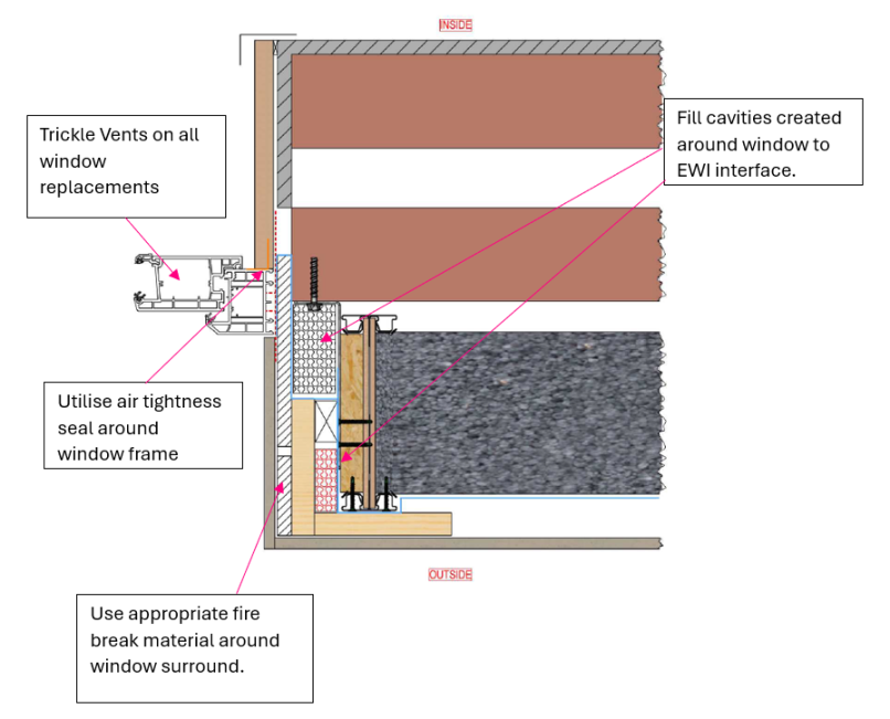
The following are critical high-level rules for a window opening that should be complied with as part of a Transform-ER retrofit programme:
- Trickle vents on all window replacements
- Fill cavities created around window to EWI interface
- Use airtightness seal around window frame
- Use appropriate fire break material around window surround
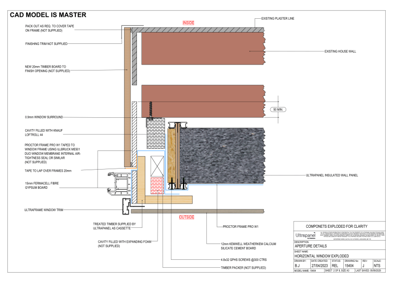
Exemplar detail
Below is an example of how Ultraframe’s system tackles a window opening and the steps/procedure put in place to ensure weather tightness, insulative properties and fire resistance are maintained:
Testing and validation
The system provider must consider how window and door opening interfaces are treated to ensure that the claimed system performances are not adversely impacted due to these interfaces.
Develop standardised detailing packages
The manufacturer should consider a range of system-compatible detail options clearly noting any site-specific adaptions required.
- Reveals – Insulated vs. uninsulated options, detailing for different frame positions.
- Heads and sills – Drip detailing to ensure water sheds away from the system.
- Cavity closures – Need to specify a suitable cavity barrier material around the opening.
These should be designed for a range of common exterior wall types and door/window configurations. Generic details and guidance are available in INCA Technical Guidance Document 06.
Design detail validation
Thermal performance
- Prevent heat loss at window/door to wall junction and reduce cold bridging.
- Psi-value modelling on defined details as per BS EN ISO 10211, BR 497 and BRE IP 1/06.
Moisture performance
- Modelling – BS 5250:2021 provides guidance on moisture management and assessment approaches e.g. hygrothermal modelling to BS EN 15026 and condensation risk analysis to BS EN ISO 13788.
- Detailing – Correct head, sill, and jamb detailing to prevent rainwater ingress. Testing at window and door junctions following CWCT TN 41 or BS EN 12865 may be appropriate. Detailing must also consider the continuity of the vapour barrier or VCL to prevent weak points in the envelope where moisture may accumulate.
Fire performance
- Combustibility – Component products making up the reveal linings within the retrofit system should be classified in accordance with to BS EN 13501-1 (reaction to fire). The reveal design should match the overall retrofit systems required performance as Approved Document B places reaction to fire classification restrictions on the usage of combustible materials depending on the height of the building, purpose group and the proximity of the external wall to the relevant boundary.
- Cavity barriers – Cavity barriers may need (see Approved Document B) to be installed around the door and window openings to adequately close any wall cavities. The cavity barrier material selected should be capable of achieving R30 and I15 when tested in accordance with BS EN 1366-4 or should meet the material description defined in ADB 2019 Section 5.21.
- System testing – If the system is intended to be utilised on buildings above 11m in height then additional care should be taken to ensure the system is safe to be installed and expert advice should be sought. Additional testing to BS 8141 may be required if the system features combustible components.
Structural performance
When evaluating the structural integrity of an EWI system around openings, manufacturers should consider:
- Reinforcement and impact resistance – Enhanced reinforcement should be used near vulnerable areas. Door openings are prone to additional impacts during usage so need to ensure the system has sufficient durability for this application. EAD 040083 offers guidance on assessment methods and levels of performance that may be appropriate.
- Fixing strength near openings – Edge fixings should withstand design loads despite proximity to openings. BS EN 13494 pull-out resistance testing for adhesive based systems.
- Support of loads above openings – Structural loads from the system (e.g., insulation/render) must be safely transferred above lintels. Use structural calculation methods from Eurocode 6 (EC6) for masonry or EC9 for metal fixings.
- Wind load effects – Openings alter wind pressure distribution – evaluate with BS EN 1991-1-4. Ensure system anchorage meets required performance.
- Movement compatibility at joints – Design for movement at junctions using sealants that comply with BS EN ISO 11600. Assess long-term performance through artificial ageing tests.
Relevance
- Fire: Proper detailing at openings can prevent the possible spread of fire through wall cavities protecting the buildings compartmentation strategy.
- Moisture: Proper detailing stops water ingress into the insulation and issues due to interstitial condensation.
- Thermal: Good detailing ensures the proposed system delivers on energy targets and is not compromised by poor interface performance.
- Structural: Need to ensure openings do not weaken resistance of system to wind loading and ensures ongoing system durability.
Site validation
Detailing should be checked after the system is installed to confirm the validity of the proposed designs. Below are a number of post-installation checks that may be appropriate.
- Thermal imaging (BS EN 13187) – Check for cold bridges at reveals.
- Blower door testing (BS EN 12114) – Verify airtightness performance.
- Moisture testing (BS 5250) – Ensure materials remain dry post-installation.
- Water penetration testing (CWCT TN 41) – Validate rainwater runoff at sills/heads