These interoperability rulesets and principles were produced by the MTC with contributions from BRE, Ultrapanel, Bow Tie Construction, Tata Steel UK, KIN and Vundahaus.
Introduction
One of the primary challenges and sources of issue or failure of retrofit measures are interfacing elements. A housing “Interface” refers to the juncture or connection point between different systems, materials, or components within a building or between a building and its external environment.
To create a comprehensive list, 140+ different interfaces were identified to exist across an array of varying building typologies and construction types. Identification of these interfaces is essential to understanding the potential challenges faced when a dwelling undergoes a retrofit. These interfaces were categorised into the following groups:
- Service penetrations
- Affixed to structure
- Perimeter
- Roofing
- Occupant additions
- Openings/ envelopes
- Internal
The intention of our work was to identify rule sets and principles that should be followed to ensure high quality, consistent retrofit. To demonstrate this, 9 high-priority interfaces were chosen as areas of focus.
Transform-ER’s 9 priority interfaces
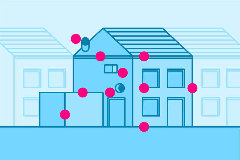
From the initial list of 140+ interfaces, the manufacturers and designers within the consortium prioritised their top 9 interfaces based on past site experience, complexity of the interface and the likelihood of failure. This led to the following list of focus interfaces being formulated:
- Window and door openings
- Eaves
- Base-to-ground
- Verge
- Party wall (roof, wall, floor, chimney)
- Wall penetrations and mountings
- Concave wall with opening
- Roof penetrations
- Abutment
You can explore the details for each of these interfaces using this grid, as well as explore more about their selection and information included below.
Transform-ER’s 9 priority interfaces

1: Window & doors
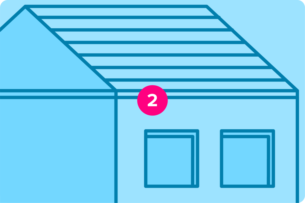
2: Eaves

3: Base to ground

4: Verge

5: Party wall

6: Wall penetrations

7: Concave wall

8: Roof penetrations

9: Abutment
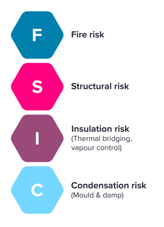
Interface categorisation
The respective selected interfaces have been assessed based upon these risk categories to highlight key areas of emphasis for each respective interface.
Standard detailing process
For the selected list of interfaces, the following process was applied to ensure both theoretical requirements and practical application of proposed solutions were considered.
| 0. Interface background | Assess opportunities to standardise the interface and the capability of manufacturers to amend products to accommodate a standard interfacing method/detail. |
| 1. Interface requirements | Identify the required level of detail manufacturers must provide to be able to develop a standard interfacing detail for a given interface. Identify critical risks regarding the interface (e.g. fire, moisture management, buildability etc). |
| 2. Ideas and concepts | Collate existing methods and details for management of the interface currently from all respective manufacturers/ designers. Select suitable option for development of standard interfacing detail – will range from minimal changes to existing products to development of a new component for interfacing. |
| 3. Build and test | Use digital validation with consortium and non-consortium-based products to ensure standard interface detail will work. Complete physical validation of concepts as part of prototyping. |
| 4. Exemplar detail | Design embodiment showcasing Transform-ER interoperability rules using consortium manufacturers’ products. |
| 5. Generate interoperability standards | From the designed solution, interoperability standards can be generated to enable onboarding of future products to Transform-ER platform. |
Testing and validation
Each retrofit project presents unique challenges due to variations in building age, construction type, architectural features, exposure conditions, and any existing construction defects.
A manufacturer cannot practically test their system for every possible scenario, but they can establish a robust set of interface details that demonstrates that their proposed system is suitable across a range of common interface conditions and compliant with the UK Building Regulations. Any new retrofit system should be able to demonstrate performance in terms of weather resistance, moisture, thermal, fire, structural and durability performance as appropriate.
The manufacturer should develop detailing solutions, validate them through modelling and testing, and provide clear installation and site-checking guidance. This ensures the retrofit system performs reliably across varied retrofit conditions while reducing risks related to interface risk category. This should also allow the details to be included within the scope of any third-party certification undertaken on the system.
Site preparation work
Definition
Construction site preparation work involves a series of pre-emptive activities carried out to ready a site for the actual construction process. These tasks are crucial for ensuring a safe, efficient, and effective construction phase. To ensure a site is correctly prepared for a Transform-ER retrofit, the subsequent guidelines are to be followed.
Guidelines
- Preparation phase to be completed 2 weeks prior to retrofit install to address any external features or potential snags – services, satellite dishes and taps below DPC level.
- Clearance of area around dwelling, enabling the accessibility required to complete the retrofit measures prescribed.
- If in good condition, are at right angles and are even, non-slip surfaces, steps are to be left as is accepting there will be a thermal bridge created by this.
- Drains must be demolished, moved or planned for with design of an insulated recess.
- External services should be run horizontally as short a distance as possible without exposure at a predefined height.